SCHWEIZER 1-23 R/C TOY CAR: PASSO 1 A FUSELAGEM (STEP 1 THE FUSELAGE)


Coloque o molde da fuselagem sobre a folha
de isopor de 1,5 cm e recorte com a resistência.
(Place the fuselage mold on 9/16" styrofoam sheet and cut with resistance.)Photo 2

Com uma lâmina acerte os cantos, seguindo
o molde.
(With a blade, define the corners by following the mold.)Photo 3

(Remove the dashed rectangle from the guide with the blade, and cut the Styrofoam. This will be the compartment of receiver and battery )
Retire o retângulo tracejado do molde com
o estilete e, através dele, recorte o isopor. Esse será o compartimento do
receptor e da bateria.
Photo 4

Revista o retângulo com balsa 1.5mm.
(Reinforce the rectangle with balsa 1/16".)Photo 5

Usando o molde do reforço, faça duas peças
com a bandeja de espuma.
(Using the reinforce mold, make two pieces with the foam tray)
Cole uma, com cola de isopor, depois corte
o segmento de isopor/balsa que vai do inicio do retângulo até o início da
cabine (ele não deve receber cola).
(Glue one, with styrofoam glue, then cut the styrofoam / balsa segment from the beginning of the rectangle to the beginning of the "cabin" (this segment should not have glue))Photo 7

Em seguida, cole do outro lado a
segunda peça, formando a caixa do equipamento. Depois de seco, lixe para
uniformizar a superfície.
(Then glue the second part, on the other side, forming the box of equipment. After drying, sand to smooth the surface.)
Photo 8

Com um arame fino, faça o canal que levará a fiação dos controles. Esse canal vai do recorte traseiro, até a caixa do receptor, atravessando a fuselagem.
(With a thin wire, make the channel for the controls wires. This channel goes from the rear cut out, until the receiver box, through the fuselage.)
Photo 9

Em seguida, usando o arame como guia, passe um tubo fino metálico para desobstruir o canal dos fios. Se preciso, aqueça moderadamente o tubo, para facilitar a passagem no isopor.
(Then, using the wire as a guide, pass a thin tube to clear the wire channel. If you need, heat the tube moderately, to facilitate passage in the styrofoam.)
Photo 10

O tubo saindo na caixa do receptor.
(The tube coming out of the receiver box.)
Photo 11

O canal dos fios pronto, atravessando a fuselagem.
(The wires passage ready, across the fuselage.)
Photo 12

Sobreponha a base da fuselagem sobre uma bandeja de espuma, risque o contorno e recorte os reforços que vão colados na parte de baixo da fuselagem.
(Overlap the fuselage base on a foam tray, cut the outline, making the reinforcement that will be glued in the edge of the fuselage.)
Foto 13

Photo 14

Cole os reforços na parte de cima da fuselagem.
(Glue the reinforcement in the top of the fuselage.)
Photo 15

Photo 16


Cole os reforços na base da fuselagem.
(Glue the reinforcement in the base of the fuselage.)Photo 14

Cole os reforços na parte de cima da fuselagem.
(Glue the reinforcement in the top of the fuselage.)
Photo 15

Observe que o reforço na parte final
da fuselagem onde vai o leme, tem um recorte, para facilitar a colagem deste.
(Note that the reinforcement at the end of the fuselage where the rudder is fixed, has a cutout, to facilitate glue.)
(Reinforce the front by gluing a strip of cornflakes card with the same width. It starts at the opening of the box and goes until amendment , passing a little.)
Photo 17

O trem de pouso do aeromodelo é composto por uma roda central e uma rodinha. Para fazer a roda central, recorte um disco 24mm em espuma dura, lixe, perfure e reforce o centro com compensado e um tubinho fino como na foto acima.
(The landing gear of the airmodel is composed of a center wheel and a rear wheel. To make the center wheel, cut a 1" disc into hard foam, sand, puncture and reinforce the center with plywood and a thin tube as in the photo above)
Photo 18

Escave a fuselagem no local indicado pela planta.
(Excavate the fuselage at the location indicated by the plant.)
Photo 19

Reforce as bordas com duas tiras de balsa, que por sua vez, serão o suporte do eixo da roda.
(Reinforce the edges with two balsa strips, which will support the wheel shaft.)
Photo 20

A roda central instalada.
(The center wheel installed.)
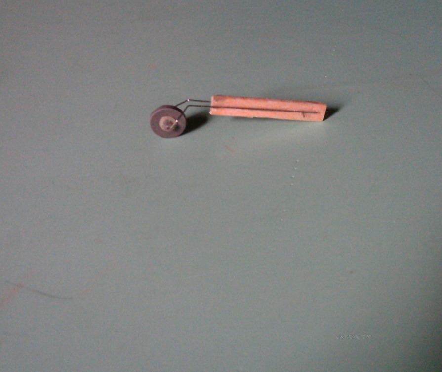
A rodinha traseira é feita a partir de um arame fino, contínuo e dobrado, preso a uma peça de balsa. A roda é recortada em borracha com um miolo de plástico.
(The rear wheel is made from a thin, continuous, folded wire attached to a piece of balsa. The wheel is trimmed in rubber with a plastic center.)
Photo 22

A roda traseira fixada na fuselagem.
(The rear wheel attached to the fuselage.)


Comments
Post a Comment